This article explores the design of bolted steel connections and how to design them based on the recommendations of Eurocode 3 part 1
Bolted connections are the most common types of connections encountered in steel structures after riveted joints. Bolted connections are very fundamental elements in steel structures. They help in providing the necessary strength and rigidity required for connecting members in steel.
In steel construction, the reliability of joints and connections is paramount. Steel connections must resist various forces, including shear, tension, or a combined tension and shear, which can significantly affect the overall stability of a structure, if not well designed. Bolted connections are versatile, and allows for easy assembly and disassembly, which is advantageous in both construction and maintenance phases.
For engineers working to the Eurocodes, understanding the Eurocode 3 guidelines is essential in order to ensure that the connections not only meet the required strength criteria but also adhere to standardized safety practices. Eurocode 3 (EN 1993-1-8) outlines the guidelines and requirements for designing bolted connections and by extensions all types of connections in steel. This code ensures that steel connections are safe, reliable, and cost-effective by providing comprehensive guidelines for various types of joints and fasteners.
This article offers an overview of the design principles and types of bolted connections and provides two detailed worked examples to illustrate the application of Eurocode 3 in practical design scenarios.
Principles of Bolted Connection Design
Bolted connections, as the name suggests, involve the use of bolts to join steel elements. These bolts can be subjected to shear forces, tension forces, or a combination of both. The design process for bolted connections is comprehensive and involves several critical steps to ensure the strength and safety of the structure. These includes:
Bolt Types
In bolted connection design, selecting the appropriate bolt type is crucial. Commonly used bolts include ordinary bolts, high-strength friction grip (HSFG) bolts, and preloaded bolts. Ordinary bolts are suitable for standard applications where moderate strength is required. In contrast, HSFG bolts and preloaded bolts are used in situations where high strength and performance are necessary. The choice of bolt type directly affects the connection’s performance under various loading conditions. Engineers must carefully consider the required performance and loading conditions to select the most appropriate bolt type for their specific application.
Bolt Grade
Bolts are classified into different grades based on their tensile strength. Eurocode 3 specifies the use of high-strength bolts, particularly grades 8.8 and 10.9, for critical connections. These high-strength bolts provide enhanced performance and reliability, making them ideal for applications where safety is paramount. Grade 8.8 bolts have a minimum tensile strength of 800 MPa, while grade 10.9 bolts have a minimum tensile strength of 1000 MPa. Choosing the appropriate bolt grade ensures that the connection can withstand the applied loads without failure, contributing to the overall safety and durability of the structure.
Load Conditions
Bolted connections must be designed to resist specific load conditions. These connections can be subjected to shear forces, tension forces, or a combination of both. The design process must consider the direction and magnitude of the applied loads to ensure the connection’s adequacy. Shear forces tend to slide the connected elements past each other, while tension forces pull the elements apart. In many cases, connections are subjected to both shear and tension simultaneously. By accurately assessing the load conditions, engineers can design connections that effectively resist these forces, ensuring the stability and safety of the structure.
Bolt Arrangements
The arrangement of bolts in a connection significantly influences its strength and behavior. Various bolt arrangements can be employed, including single shear, double shear, and staggered patterns. In single shear arrangements, bolts are subjected to shear forces in one plane, while in double shear arrangements, bolts are subjected to shear forces in two planes. Staggered patterns distribute the forces more evenly across the connection, enhancing its strength. The choice of bolt arrangement depends on the specific requirements of the connection and the applied loads. Proper bolt arrangement ensures that the forces are effectively transferred, and the connection remains robust.
Design Checks
To ensure the safety and reliability of bolted connections, several design checks must be performed. These checks include verifying the bolt shear strength, bearing strength, and tension strength. Additionally, the interaction between shear and tension forces must be considered. The bolt shear strength check ensures that the bolts can resist the applied shear forces without failing. The bearing strength check ensures that the connected elements can withstand the bearing stresses induced by the bolts. The tension strength check ensures that the bolts can resist the applied tension forces. By conducting these design checks, engineers can confirm that the connection meets the necessary strength criteria and adheres to Eurocode 3 guidelines.
Understanding and applying these principles in bolted connection design allows engineers to create safe and reliable steel structures. Each principle plays a vital role in ensuring that the connections can withstand various loads and stresses, contributing to the overall stability and integrity of the structure
Types of Bolted Connections
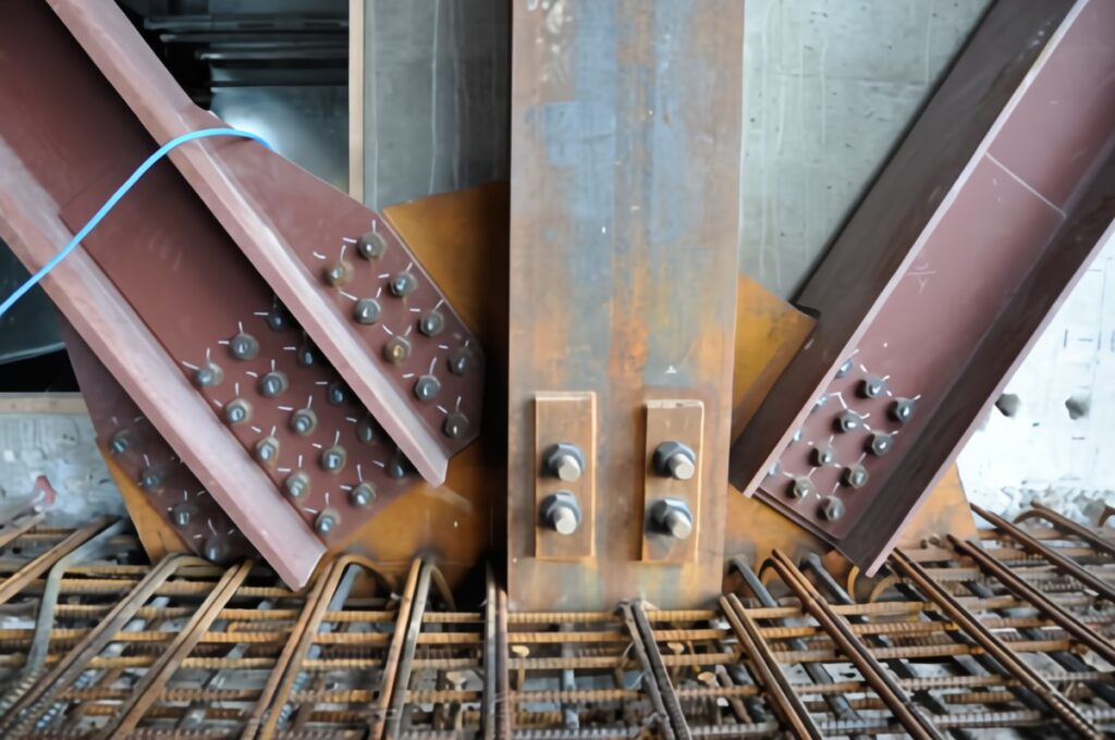
Bolted connections (Figure 1) come in various forms, each with its specific application and advantages. Understanding the different types of bolted connections is essential for designing robust and efficient steel structures. Here, we explore the primary types of bolted connections used in steel construction.
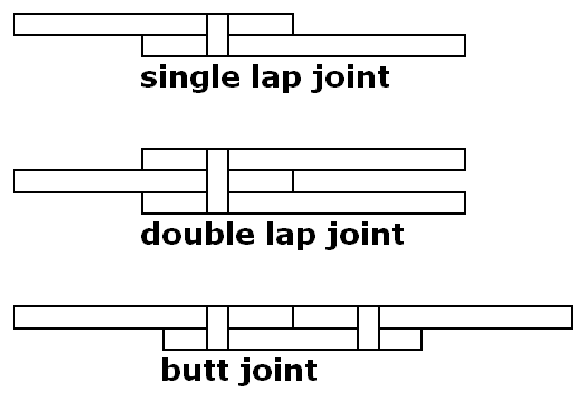
Lap Joints
Lap joints are one of the simplest forms of bolted connections. In this type, two steel plates overlap each other, and bolts join them together. This straightforward design makes lap joints highly effective for connecting secondary structural elements where simplicity and speed are essential. Engineers often use lap joints in applications such as bracing and minor connections due to their ease of installation and cost-effectiveness.
Butt Joints
Butt joints involve aligning two plates end-to-end and joining them with bolts through a cover plate. This type of connection is critical in primary structural elements where precise alignment is crucial. By ensuring that the ends of the plates meet perfectly, butt joints provide a strong and continuous connection. They are commonly used in main structural members such as beams and columns, where the integrity and alignment of the connection directly impact the overall stability of the structure.
End-Plate Connections
End-plate connections are used to connect beams to columns or other beams. In this connection type, an end plate is welded to the end of a beam and then bolted to the supporting element. This method provides a robust and secure connection, capable of handling significant loads. End-plate connections are particularly advantageous in steel frame structures, where the connection needs to transfer both shear and moment forces efficiently.
Fin Plate Connections
Fin plate connections feature a plate (fin) that is welded to the supporting structure, with the beam bolted to this fin plate. These connections are commonly used in simple beam-to-column connections where ease of installation and flexibility are important. Fin plate connections offer a straightforward and effective way to connect beams to supporting structures, making them a popular choice in many steel construction projects.
Moment-Resisting Connections
Moment-resisting connections are designed to resist both bending moments and shear forces. These connections are crucial in frames where rigidity and stability are required. By providing a strong and stable connection, moment-resisting connections ensure that the frame can withstand lateral loads such as wind and seismic forces. These connections are essential in the design of multi-story buildings and other structures where maintaining the overall stability of the frame is critical.
Design Example 1: Single Shear Lap Joint
Problem Statement
Design a single shear lap joint to connect two steel plates using M16 bolts of grade 8.8. The plates are subjected to a shear load of 50kN. The thickness of each plate is 10 mm, and the steel grade is S275.
1. Determine Bolt Shear Capacity
The shear capacity Vb of a bolt is given as:
V_b=\frac{f_u\times A_s}{\gamma_s}Where:
- fu = ultimate tensile strength of the bolt (800 MPa for grade 8.8)
- As = shear area of the bolt (π/4 × d2 for M16 bolt, where d = 16 mm)
- γM2 = partial safety factor for bolts (1.25)
A_s=\frac{\pi}{4}\times 16^2= 201mm^2V_b=\frac{800\times201}{1.25}=128.64kNSince the design shear load is 50 kN, one bolt is sufficient. However, considering safety and redundancy, we use 2 bolts.
2. Determine Plate Bearing Capacity
The bearing capacity Vb,p of the plate is given by:
V_{b,p}=d\times t \times f_u/\gamma_{M2}Where:
- d = diameter of the bolt (16 mm)
- t = thickness of the plate (10 mm)
- fu= ultimate tensile strength of the plate material (430 MPa for S275)
- γM2 = partial safety factor for plates (1.25)
V_{b,p}=16\times10\times430/1.25=55.04kNEach bolt’s bearing capacity is 55.04 kN. For two bolts, the total capacity is 110.08 kN, which is adequate.
3. Bolt Arrangement
The bolts should be arranged to minimize eccentricity. The minimum edge distance and spacing should comply with Eurocode 3 recommendations.
- Minimum edge distance = 1.2d = 1.2 × 16 = 19.2 mm
- Minimum spacing = 2.2d = 2.2 × 16 = 35.2 mm
In this case, the design is safe and satisfies the Eurocode 3 requirements.
Design Example 2: End-Plate Connection
Problem Statement
Design an end-plate connection to join an I-beam (HE 300 B) to a column using M20 bolts of grade 10.9. The beam is subjected to a shear load of 100 kN and a bending moment of 150 kNm.
1. Determine Bolt Shear & Tension Capacity
The shear capacity Vb of an M20 bolt (grade 10.9) is:
V_b=\frac{f_u\times A_s}{\gamma_s}Where:
- fu = ultimate tensile strength of the bolt (1000 MPa for grade 10.9)
- As = shear area of the bolt (π/4 × d2 for M20 bolt, where d = 20 mm)
- γM2 = partial safety factor for bolts (1.25)
A_s=\frac{\pi}{4}\times 20^2= 314mm^2V_b=\frac{1000\times314}{1.25}=251.2kNThe tensile capacity Tb of the bolt is:
T_b=\frac{f_u\times A_t}{\gamma_s}Where:
- At= tensile area of the bolt (determined from bolt manufacturer data, typically around 245 mm² for M20)
T_b=\frac{1000\times245}{1.25}=196kN2. Design for Shear and Moment
Considering the combined effect of shear and moment, the bolts will experience both shear and tensile forces. The interaction is checked using the following criterion:
(\frac{V}{V_b})^2 + (\frac{T}{T_b})^2 \le1For the given loads:
- Shear force per bolt = 100 kN / 4 bolts = 25 kN
- Tensile force per bolt = M / (bolt group moment arm) = 150 kNm / (0.3 m) = 50 kN (assumed moment arm)
(\frac{25}{251.2})^2 + (\frac{50}{196})^2 =0.0751<1Therefore, the design is safe.
Bolt Arrangement and Plate Design
The end plate should be designed to ensure proper bolt spacing and edge distances. The plate thickness is selected based on the bending moment and shear forces. Using standard practices and Eurocode 3 guidelines, a 20 mm thick end plate is selected.
Verification of Plate and Welds
The plate and welds must also be checked for capacity. The plate should be checked for bending and shear, while the welds should be checked for strength. Standard weld design procedures can be applied using Eurocode 3 recommendations.
Also See: Design of Welded Connections to Eurocode 3| Worked Example
Conclusion
Designing bolted connections requires mastering the code guidelines and skillfully applying them to real-world scenarios. The provided examples vividly demonstrate the process of designing single shear lap joints and end-plate connections, emphasizing the key considerations and calculations.
Hi my name is Mohsin and I have noticed a few issues in your website and I’d love to help you fix them. I am an SEO specialist and I help small businesses to get more business using their website. If you want me to send the list of issues, Please reply YES
why is the tensileforce per bolt is 50 Kn When the assumed moment arm is 0.3; M/moment arm 150/0.3= 500kN